| The Boiler |
|
|
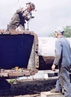
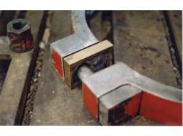
Even with all the rivets drilled out, the foundation
ring was still held very firmly between the boiler plates and a
considerable “pull” and a great deal of banging was needed to get it
out. Eight sections of U channel were fixed onto studs screwed into the
ashpan mounting stud holes and braced against the inner and outer firebox
plates. By screwing down the nuts very tightly onto the studs an even pull
was exerted all round the ring. By hammering with sledge hammers on the
outer steel plates (but not the soft, inner copper ones) and continually
tightening the nuts, the ring was persuaded to move. In the picture Steve
is hammering while Jeff takes a breather.
|
 |
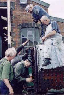 |
Jeff, having shown how it should be done, applied some
leverage while everyone else joined in with the heaving and hammering to
gradually ease the ring out a few thou at a time. The picture shows Jeff
levering, Roy applying oil, Steve and Derek tightening while Keith
supervises.
|
|
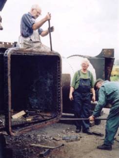
Here
the ring is about to drop out. On the left it is free of the boiler plates
and Roy and Jerry are levering it away from the top right corner where it
is still held while Keith continues to supervise. |
 |
| The Motion |
|
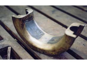 |
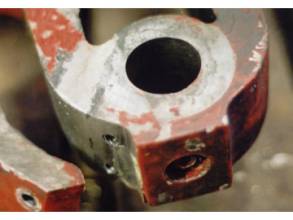
All the main components of the motion have been removed
for examination. In one big end bearing an overheating problem had caused
the white metal to melt and run into the felt cavity (see picture)
obstructing the oil way.
|
| The Springs |
|
| The springs are in good shape although part of the
buckle will have to be replaced on the two rear springs due to banana
shaped holes having formed.
|
| Eccentrics |
|
| The eccentric bearings were worn and will require
renewal of the white metal liners. The intention is to cast and machine
the liners at the ESR. This will be quite a challenge as the machining
will have to be done on the assembled straps which are over 24” in
diameter. Fortunately the railway possesses an ancient Mitchell lathe
which has sufficient clearance between the bed and the chuck to enable the
whole assembly to be mounted on a face plate for turning.
|
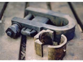
| The picture shows an eccentric spacer which has had a
pin added to prevent it turning.
|
 |
 |
The left hand expansion link was found to be cracked.
The crack had been welded before and supported with an additional strap
screwed onto the outside, but the weld had cracked again. In the picture
the crack can just be seen running down the middle of the bright area of
weld. The link will be welded again and we will need to investigate stress
relieving to prevent the crack recurring.
|
| Small Ends |
|
| One small end bearing came out in three pieces possibly
as a result of the wedge having been driven in too hard. A new bearing
will be machined.
|
 |
| Valve and
Cylinders |
|
|
The cylinders pistons and rings all look to be in good
condition and will need no repairs.
In service the E1 suffered
from an oscillating motion which, despite the best efforts and all the
brain power of the loco shed, could not be cured. A key part of the
examination of the valves was therefore to look for any fault which might
cause this. The cylinder covers, valves and pistons were removed to permit
the cylinders and valve ports to be inspected.
With the valves removed it was noticed that the valve
seats had worn by about 12 thou at each end. This could allow the valve to
rock on the inside exhaust valve seat face and admit steam to both ends of
the cylinder at once. If this permitted steam to enter the cylinders too
early in the cycle it could very well be the cause of the oscillation.
Clearly the valve seats have to be machined flat again
but access to them is very restricted. Originally the cylinder block,
which is in two halves, would have been machined off the loco making
access to the seats easy. But to extract the five ton block from the
frames, possibly for the first time since the loco was built, split it and
put it back again after machining would not be a Sunday afternoon job to
say the least! An alternative method has been devised by Steve Masters
which involves a special purpose machine to enable the seats to be
machined in situ. Currently the machine has been designed and is being
manufactured in the workshops.
|
|
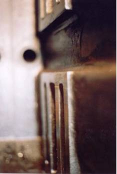
The picture is of the lower left hand valve port viewed
from the front of the cylinder block. A witness mark at the edge of the
worn area can be seen in the centre of the picture. A special machine is
being built to enable the machining to be carried out in situ.
|
 |
|
|